WESTPORT TERMINAL RR |
BLT 2000 update 2003 |
[How to scratch build turnouts] and [crossings] [Manual thrown Peco turnouts] [switch stands] [Movable magnets] [DCC] [beacon light] [CB&Q 173] [RS-1 and weathering] [tender pick up 0-8-0] [ Track Cleaning Transfer Caboose ] [ Signal Bridge ] [Operation] [Way of Hopper BN 25 3 84] [WT RR industries shipping & receiving] download Excel [carcards&waybills] 900kB [staging] [Harbor District] [Plywood District] [Third Street Industrial District] [track scale, structures] [Operating gates] [Waterfront Structures] [trestle] [Interchange Cars] [car exchange] [pass exchange] [electronic rail pass ] [ video ] |
WESTPORT TERMINAL RR goes DCC
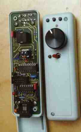
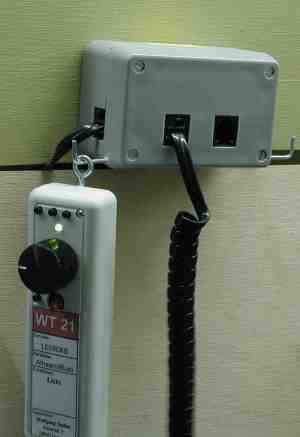
I built ten throttles, called FRED
and bought 10 LocoNet boxes and cables.
I bought the Intellibox from Uhlenbrock and two booster from Lenz according to the suggestions from my friends. And now I'm installing decoders. But I do not only install the decoders. I replace the bulb with white LEDs. And I use yellow LEDs for working beacon light |
 |
 |
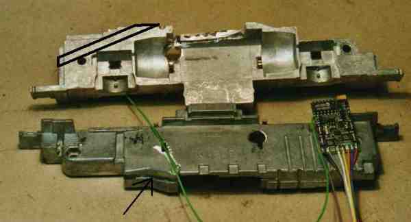
One of the first engines was a Kato NW2. This is the engine you have problems to lift off the shell!
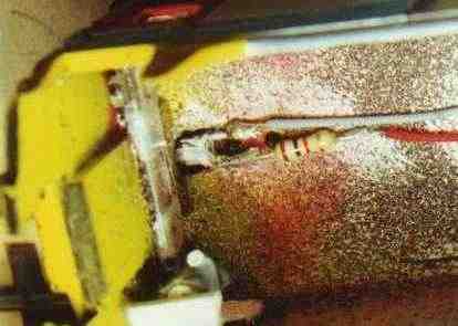
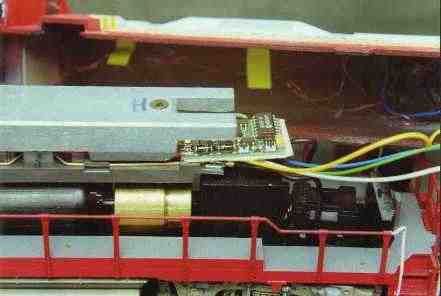
| My engine, WT 16 named after Henry Bell got a decoder from Kuehn, a T140 with four functions. I used three functions for headlight, rearlight and beaconlight. The room for the decoder I made just above the
I've marked the place in the picture with black |
 |
|
| There're some groves. These are the channels for the wires from pick up sheets and lights to the decoder. I replaced the yellow front LED by a white LED. I changed it on the little PC board together with the resistor. I used a 1 kOhm resistor for the white LED. Thes reduces the current and gives a bright light. Don't forget to remove the current pads on the PC to the two halfs of the body! |
 |
|
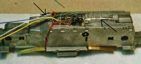
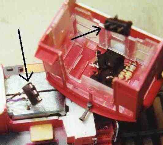
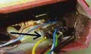
| This picture shows the cab of
the NW2. For better maintanance I used a plug. The two arrows show at
the two plugs. They are made of IC sockets. Also you can see the white LED which I painted black. Whithout painting the LED would illuminate the cab! The two resistors are for the white LED You can see that I shortened the legs of the LED to about 5 mm (0.25''). For more information look at |
 |
|
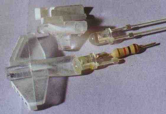
Light in RDC
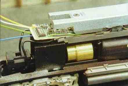
| The RDCs got a white LED at each side.
This picture shows the LED with the shortended legs. On one legs I soldered the 1 kOhm resistor. I glued LED and wires to the roof. I used also a "IC-socket made connection". |
 |
Kato's GP 35
|
||
|
||
|
I've got a soundtraxx DSX decoder an built it to my RDC WT 11.
Still any questions? Write to Wolfgang Dudler
next top
| [How to scratch build turnouts] and [crossings] [Manual thrown Peco turnouts] [switch stands] [Movable magnets] [DCC] [beacon light] [CB&Q 173] [RS-1 and weathering] [tender pick up 0-8-0] [ Track Cleaning Transfer Caboose ] [ Signal Bridge ] [Operation] [Way of Hopper BN 25 3 84] [WT RR industries shipping & receiving] download Excel [carcards&waybills] 900kB [staging] [Harbor District] [Plywood District] [Third Street Industrial District] [track scale, structures] [Operating gates] [Waterfront Structures] [trestle] [Interchange Cars] [car exchange] [pass exchange] [electronic rail pass ] [ video ] |