WESTPORT TERMINAL RR |
BLT 1999
|
[How to scratch build turnouts] and [crossings] [Manual thrown Peco turnouts] [switch stands] [Movable magnets] [DCC] [beacon light] [CB&Q 173] [RS-1 and weathering] [tender pick up 0-8-0] [ Track Cleaning Transfer Caboose ] [ Signal Bridge ] [Operation] [Way of Hopper BN 25 3 84] [WT RR industries shipping & receiving] download Excel [carcards&waybills] 900kB [staging] [Harbor District] [Plywood District] [Third Street Industrial District] [track scale, structures] [Operating gates] [Waterfront Structures] [trestle] [Interchange Cars] [car exchange] [pass exchange] [electronic rail pass ] [ video ] |
How to scratchbuild turnouts
download Excel sheet for clearance calculation carclearance.xls
Diese Seite auch auf
Deutsch. ![]()
still in work - any help and comments appreciated
In 1987 I built the first turnouts for the Station Naumburg. One kit consists of one template, nails, pregauged rails and cuttet ties.
The Results didn't please me for long. And with Tips from the Fremo Meetings I startet to build the turnouts myself. Since then I built nearly a hundred turnouts by myself. The ties are out of Pertinax. But in some parts I use wooden ones instead. This saves the Pertinax ties which are very hard to saw.
And here's the latest HowTo, building a code 40 narrow gauge turnout.
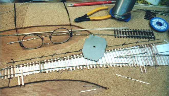
Tools:
NMRA gauge, soldering iron with small tip, tweezers, rail cutter, needle file, razor saw, electric saw with sanding wheel
And now the work:
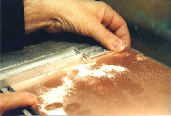
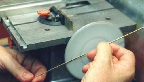
You need lots of ties. the cutting table circular saw is a big help. Here I'm sawing strips. This "Pertinax" sheet is made of hardpaper and 200mmx300mm (8''x12'') big. It's covered with .005 copper coating. So I get long stripes and cut the desired tie length.
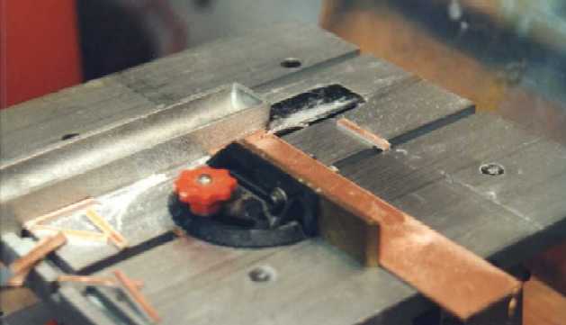
For the mostly used ties I saw a stockpile.
This work makes a lot of dust so it is better to do it outside during summertime. Make a stockpile!
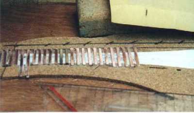
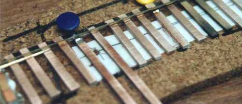
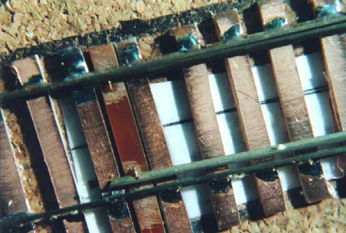
This picture shows the first glued ties. I not only marked the centerlines, but also the bounding lines for the ties. This makes it easier to get the right place for the ties. You may check the right angle easily with a Set Square.
You can see two wooden ties in the pic. When you glue all of the ties, it will dry over night. Then you can sand the Top with sanding paper.
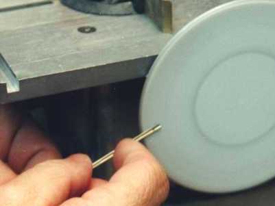
Now you can prepare the first rail, a straight stock rail.
With a marker you hatch the bottom of the rail where it will get hit from the movable points.
Here you must, in order to get room for the switch point,
remove the foot of the rail. That can be done with a file. For lazy people
there are electrical assistance. Proceed carefully, so that the rail does
not get too hot. Then it becomes dark! At the place, where the switch
points touch the stock rail, remove much of the rail bottom. Toward
the frog, let it run out
slowly decreasing the amount removed. The rail head is not weakened.
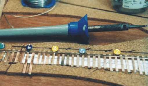
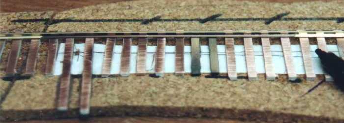
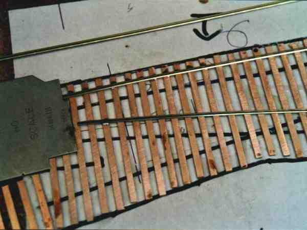
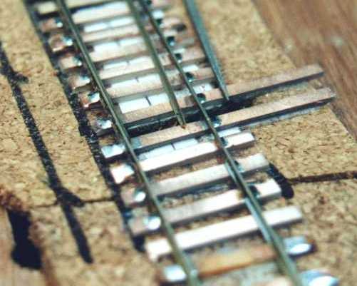
Now to soldering. The profile is placed with the help of the NMRA gauge off the center line and soldered on in two places - 1 and 2 in the picture. If the examination satisfies, solder the next places.The eye helps control achieving an even curve. It should be soldered on in the end about each sixth threshold. If readjustment is needed, the soldered connection is heated and the rail shifted.. Occasionally always check with the eye and the gauge. The picture shows the result:
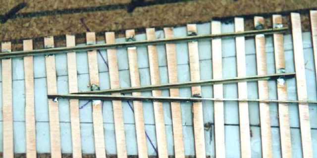
Now it goes to the frog! First the branching track is made. The point is prepared again with the help of the grinding wheel.
 |
top |
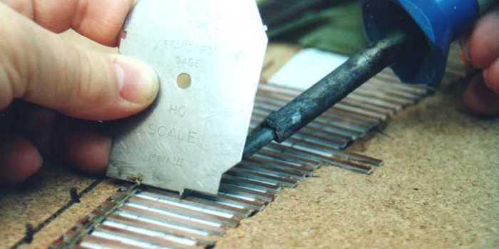
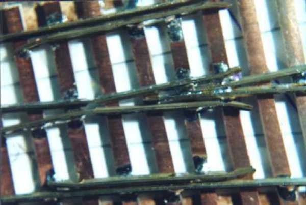
With the gauge the position of the point is determined. Pay attention on the one hand to the distance from straight the stockrail and on the other hand the distance from the center line of the branching track. If the position is correct, the track 15 to 20 ties far away from frog is soldered on. Now the correct position can be again checked and soldered on frog. This is via soldering about 5 ties away from the point.
Now the other rail is completed.
The next step is soldering the internal (curved) stock rail. This takes place first with the gauge in the frog area.Then toward points. Always solder the rail when the gauge is on the center line. It is sufficient to solder each sixth tie.
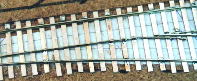
Now I solder the closure rail which is next to the straight stock rail. I place the rail to suit and solder the end closest to the points.
Now add the other closure rail, and treat it the same way.
After doing the closure rails, the point rails are done in turn. When sharpening the machine is again an important assistance. (however not too strongly, otherwise the rail does discolour. Too hot!)
Before adding points, you should solder all ties to the stock rail. Within the area, the points contact to stockrails, unnecessary tinsolder must be removed. With a file!
It is meaningful to fasten first one point rail and then to readjust the other stockrail if necessary according to the gauge.
Likewise beforehand the hole for the holding wires can be bored or cut in the soft cork.
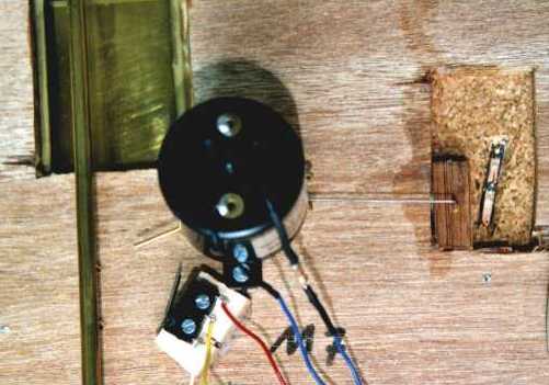
And this is the motor drive with micro switch for frog power. On the left you "see"the movable Kadee magnet.
Still any questions? Write to Wolfgang Dudler
next top
| [How to scratch build turnouts] and [crossings] [Manual thrown Peco turnouts] [switch stands] [Movable magnets] [DCC] [beacon light] [CB&Q 173] [RS-1 and weathering] [tender pick up 0-8-0] [ Track Cleaning Transfer Caboose ] [ Signal Bridge ] [Operation] [Way of Hopper BN 25 3 84] [WT RR industries shipping & receiving] download Excel [carcards&waybills] 900kB [staging] [Harbor District] [Plywood District] [Third Street Industrial District] [track scale, structures] [Operating gates] [Waterfront Structures] [trestle] [Interchange Cars] [car exchange] [pass exchange] [electronic rail pass ] [ video ] |