 |
Wolfgang Dudlerbuilding turnouts |
 |
|
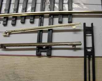
I've also followed the original Central Valley instruction.
But I had to rework the parts. The "Throw-Bar" has notches for the
tip of the points.These notches are not wide enough. I used a file. Also,
I sharpened the points. - And I soldered a thin wire to the other end of the
points. This will give a good contact with stock rails. With some castings
I had to rework the tie block. It was not wide enough for the "Throw-Bar".
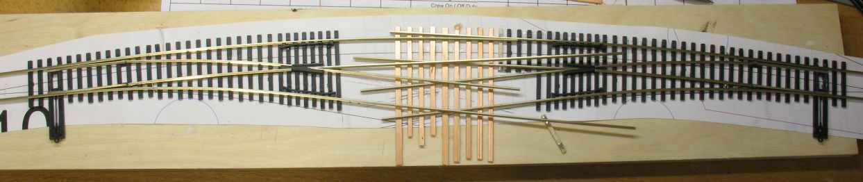
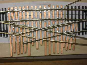
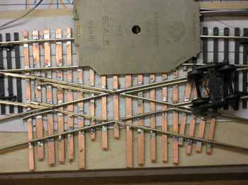
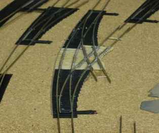
Now I need a crossing. There're the two right and left hand turnouts and between a crossing. And all at a curve.
I decided to solder the crossing. I printed the track plan 1:1
from AutoCAD and glued PC board ties between the turnouts. Radius from the
"straight" leg about 1500 mm, diverging route I didn't measure.
![]()
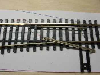
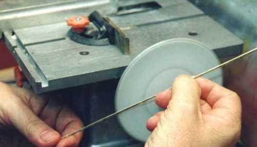
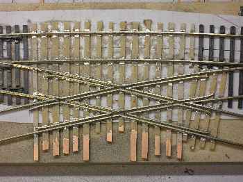
And now, it goes step by step. My tools are soldering tools, Xuron rail nipper, files, my table saw with grinding disk and NMRA gauge.
At first I soldered the connecting track. Then I worked step by step. You have to take your time. Each piece of rail must suit in its place.
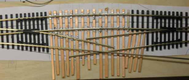
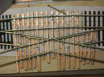
An important test tool is a truck. But I use more the NMRA gauge. In the last pic you see a working crossing. What comes next is time consuming: guard rails. You neet quite a few.
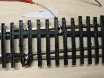
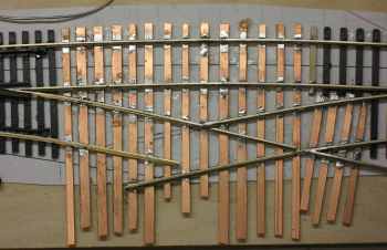
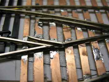
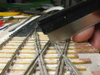
With this part finished I removed the copper foil - what a mess
![]() - and cut with a fine saw
the needed gaps.
- and cut with a fine saw
the needed gaps.
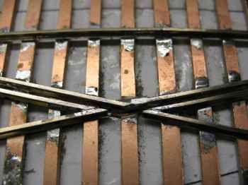
But with the points from a few turnouts I run into a problem. The points were not sure kept down. So I soldered a very small piece of very thin wire to the points. This piece glides under the "throw bar" and will - hopefully - keep the points in the correct place.
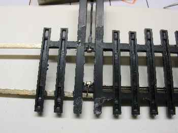
And all together

for a crossing is no problem. With DCC it is much more easy. The crossing is powered by one turnout. The possition of the other turnout should not show a route over the crossing too. That's unlogical and forbidden. In this case the frogs of the crossing have not the correct polarity. Also look at Allan Gartner's site.
or download the .pdf
next - Back to Diamond Valley